Cassette joint
The long headbox is divided at a controlled interface, with the external profile line, fastening and sealing checked after assembly.
03 · Ultra-wide & ultra-high
Three engineered platforms address transport length, ultra-wide span and exceptional height with visible structures and project-specific verification.
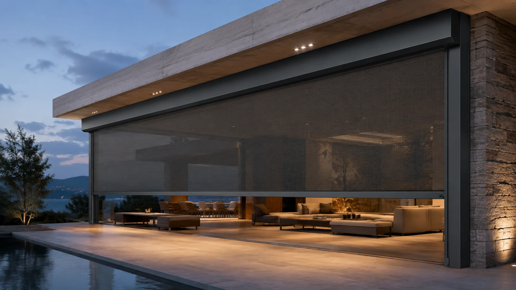
Special-format comparison
The correct system depends on what creates the difficulty: transport length, opening width or opening height.
| Platform | Designed to solve | Key structure | Manual reference |
|---|---|---|---|
| WR120C | Long components that are difficult to transport or bring to site | Engineered splice joints in cassette, roller tube and bottom rail | Ultra-wide spliceable system |
| WR150–220 | Very wide engineering openings | Large cassette, double-layer guidance, upgraded tube, drive, support and connectors | Illustrated above 5 m wide and 3.5 m high; calculation required |
| WR160–190 | Exceptionally tall openings | 160 × 190 mm cassette, Ø90 heavy-wall tube, three-piece tracks and heavy-duty guides | Illustrated theoretical height up to 10 m; engineering verification required |
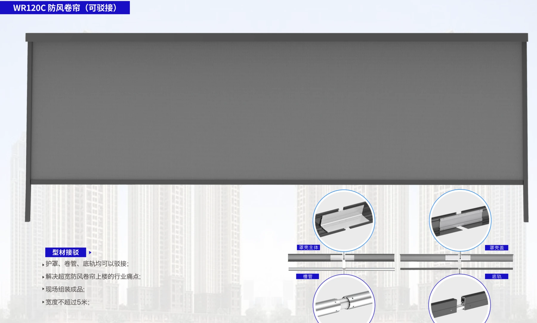
16 · WR120C
The complete manual plate shows the finished blind and the joint details used to divide long primary components for transport and systematic assembly.
08 · Ultra-wide jointing technology
The jointing method extends the system beyond normal transport length while keeping the cassette, roller tube and bottom rail connected to the same alignment and approval logic.
The long headbox is divided at a controlled interface, with the external profile line, fastening and sealing checked after assembly.
An internal connector maintains strength and concentricity so the assembled tube can rotate without an uncontrolled step or eccentric run.
The bottom rail is joined to maintain straightness, visible alignment and coordinated movement across the ultra-wide blind.
Joint position, strength, concentricity, interface sealing, fabric alignment and site assembly accuracy are verified before release.
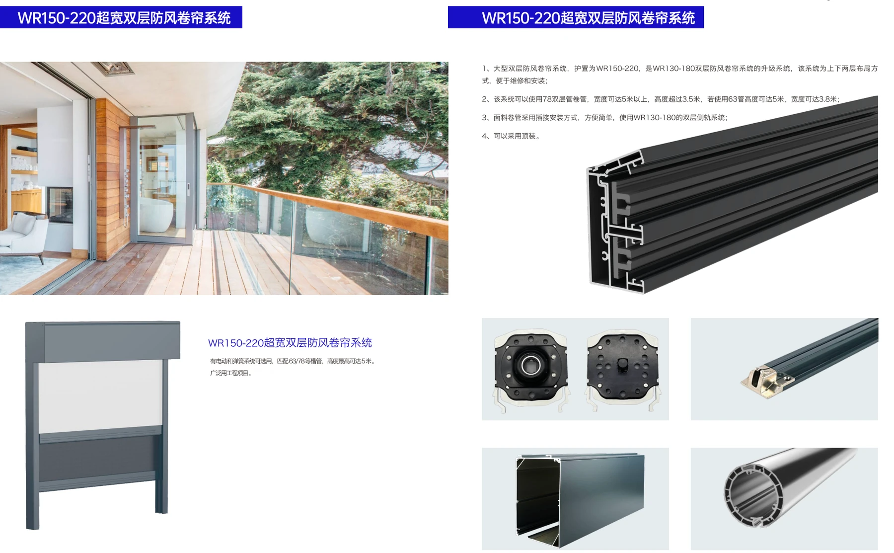
17 · WR150–220
The manual plate includes an architectural application, overall blind, large cassette, end support, track, bottom rail and roller-tube details.
WR150–220 system logic
Tube selection, guidance layers, support, connectors and drive capacity are upgraded as one coordinated assembly.
Large balcony, façade, terrace and commercial openings where standard ZIP systems no longer provide the required span.
Large cassette, double-layer ZIP guidance, selected roller tube, upgraded drive supports and reinforced connection points.
Finished opening, applied wind pressure, fabric weight, tube deflection, supports, interfaces and installation access.
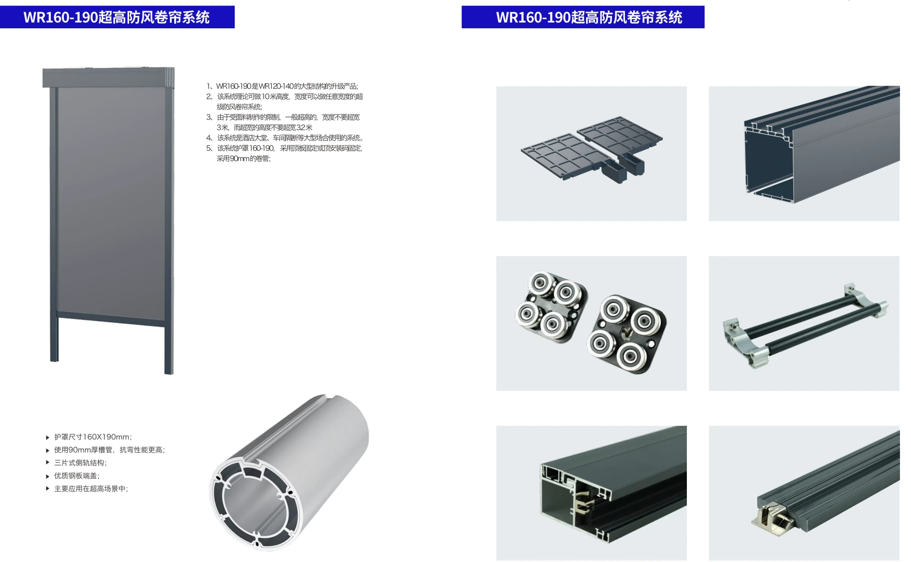
18 · WR160–190
The complete plate shows the tall-format blind, Ø90 heavy-wall tube and the heavy-duty connection, cassette and guidance components.
WR160–190 system logic
The theoretical height reference does not replace project verification. Height, width, applied pressure, tube deflection, support and site interfaces remain connected.
| Item | Product information |
|---|---|
| Main structure | 160 × 190 mm cassette; Ø90 mm heavy-wall roller tube; three-piece tracks and heavy-duty guides |
| Reference capacity | Illustrated theoretical height up to 10 m; not a universal maximum |
| Required checks | Opening width and height, wind load, fabric weight, tube deflection, support spacing and site interfaces |
| Approval basis | Project calculation, production drawing, itemised BOM and approved sample |
Materials, options and service
We match the structural platform, materials, drive, fabric and documentation to the opening instead of treating size as the only input.
Engineering aluminium tubes, heavy-wall tubes, double-layer tracks, multi-piece guides and project-matched support or splice structures.
6063-T5 aluminium profiles, die-cast aluminium parts, 304 stainless or approved weather-resistant connectors and matched sealing components.
Blackout or solar-control fabrics from YUMA, XIDAMEN or Phifer, combined with project-matched motor, torque, control method and cable outlet.
Technical selection, drawings, itemised BOM, material and colour schedule, approved samples, packing plan and Singapore delivery coordination.
Project calculation · Production drawing · Itemised BOM · Approved sample · Site assembly method · Packing and shipping documents
Engineering verification
Special-format supply is released only after the opening, loads, interfaces and assembly method are made explicit.
Confirm finished width, height, quantity, mounting condition and interface dimensions.
Define wind load, fabric weight, tube deflection and required support conditions.
Verify joints, supports, sealing, clearances and site assembly accuracy.
Release against project calculation, production drawing, itemised BOM and approved sample.
Project enquiry
Share the size and requirement. We will help structure the system, fabric, controls, documents and delivery.
WhatsApp +65 9136 0873 ↗